Entry/Exit Criterion
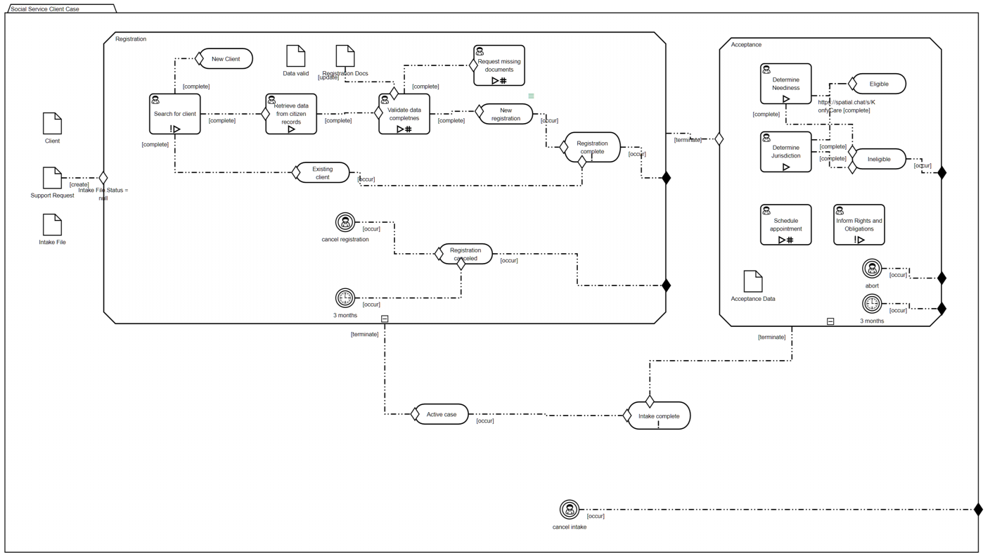
In real-world case logic, activation or termination of a plan item is modeled using entry and exit criteria. In the diagram above, those are the dash-dot connectors labeled with the standard event of the triggering item at the tail end, leading to a diamond shape called a Sentry on the boundary of the triggered plan item. A white Sentry indicates an entry condition; a black Sentry indicates an exit condition.
The criterion has two parts. The ON-part, specified by a standard event of the triggering plan item or file item, specifies when entry occurs. In the diagram it is the label of the connector, and the triggering item is the shape at the tail of the connector, i.e. the end without a Sentry. The IF-part, specified by a FEEL Boolean expression of case file items, is an attribute of the Sentry. While it is not required by the spec, the book CMMN Method and Style recommends labeling the Sentry with this expression so it is visible in the diagram.
A Sentry with no ON-part link is triggered when its containing stage becomes Active and the IF-part condition is true. A Sentry with no defined IF-part condition is triggered when the ON-part standard event occurs.
Drawing and Configuring the Link
Assuming the triggering and triggered items are placed in the diagram, start by hovering over the triggering item to see its Smart Arrows.
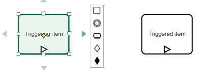
Select the appropriate Sentry shape - white or black diamond - and drag to the boundary of the triggered item until it is highlighted in green.
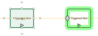
Then drop the Sentry. This creates the link.

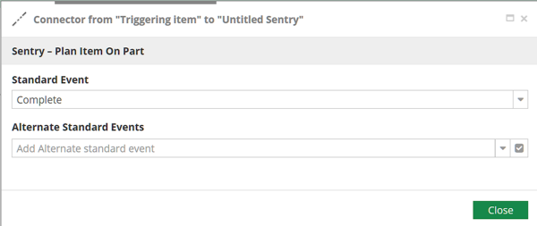
A default standard event will be selected, but you can change it from the Attributes/Standard Event action.
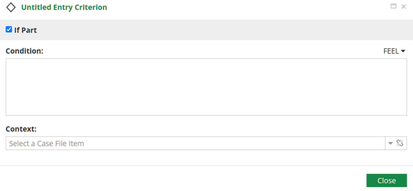
The Attributes/If Part action on the Sentry defines the condtion. If the checkbox at the top of the dialog is unchecked, the IF-part is true by default. If checked, enter a FEEL Boolean expression of case file items in the Condition box. Currently Case Modeler ignores the Context box.
