Decision Requirements
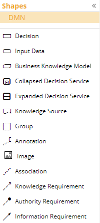
The network of all dependencies of any Decision in the model is called the model’s Decision Requirements Graph, or DRG. It is created in the form of one or more Decision Requirements Diagrams (DRD) by dragging DRG Element shapes onto the diagram canvas and linking them with information requirements and other connectors. A DMN model has exactly one DRG, which is defined and visualized as one or more DRDs. A DRD may hide or omit certain DRG elements. In addition to model elements with execution behavior, the DRD may display supplementary information or metadata, including Knowledge Sources and information overlays. For example, in the DRD below, an overlay displays the datatype of each DRG Element.
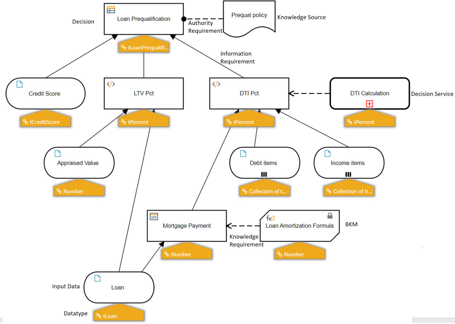
The value of each decision in the model is calculated based on the values its requirements, which are the decisions and input data directly connected by incoming solid arrows called information requirements, along with any Business Knowledge Model or Decision Service connected by an incoming dashed arrow called a knowledge requirement. The formula calculating that output value, called the decision’s value expression, may reference only the values of those requirements. The DRD in combination with the defined datatype of each DRG Element provides a complete outline of the logic dependencies. Adding the value expressions of each DRG Element makes the model executable.
DRG Elements
Every DRG Element has a shape, standard properties, and execution behavior precisely defined by the DMN standard. The names of all DRG Elements in a model must be unique.
Decision
The rectangle shape denotes a decision. It has a name, datatype, information requirements, and a value expression that returns an output value from the values of its information requirements.
Input Data
The oval shape denotes input data, meaning a value supplied at execution time. It has a name and datatype but no value expression.
Business Knowledge Model
A rectangle with two clipped corners denotes a business knowledge model, or BKM. A BKM is a user-defined logic function. It has a name, datatype, parameters, and a value expression of parameter values. A dashed connector called a knowledge requirement linking a BKM to a decision means the decision invokes the function by passing values to its parameters and receives in return the BKM output value.
Decision Service
A bold rounded rectangle denotes a decision service invoked by a decision in the model. It has a name, datatype, parameters, and logic defining its output value based on its parameter values. In a DRD depicting the invocation, the decision service is shown collapsed with a knowledge requirement to its invoking decision. The decision service’s logic is not a single value expression but a standalone DRD, in which the decision service is represented as an expanded rounded rectangle.
Knowledge Source
The wavy-bottom shape is a Knowledge Source, linked to some other DRG Element by an Authority Requirement. A Knowledge Source is a link to background information about the decision logic. It has no execution semantics in the model.
Artifacts
Artifacts are diagram shapes and connectors that are just visual annotations, having no execution semantics. The left square bracket and enclosed text is a Text Annotation. A dash-dot rectangle called a Group is used to call attention to a its enclosed elements. Image is a user-provided graphical annotation inserted in the diagram.